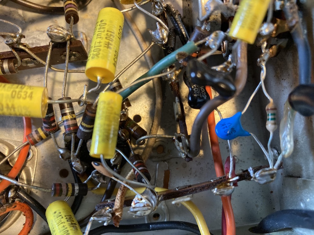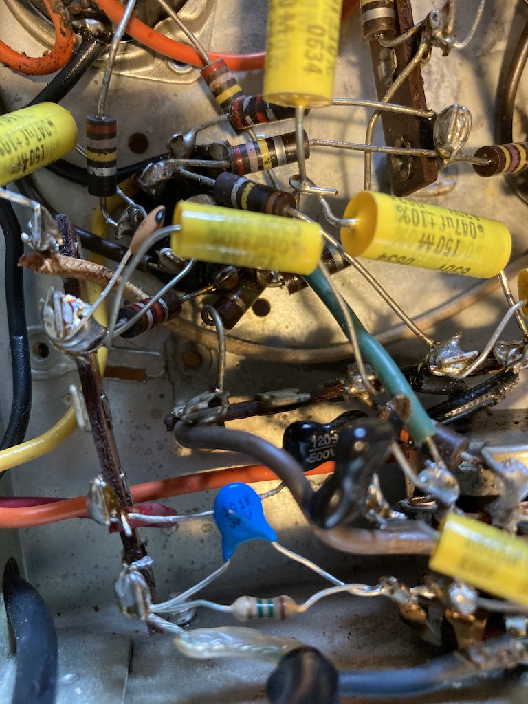
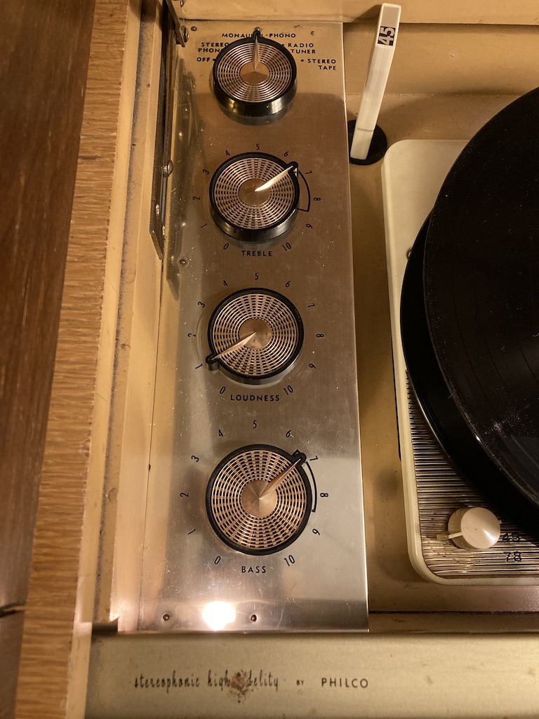
I’ve been working for years on a Philco Console “Stereo” from 1959. It came into my life via a grad student who was moving on and had no room for it, it being non-functional, merely a cool piece of furniture that took up too much space. I looked it over and got to work. Missing tubes was the least of its problems. I learned at that point about “re-capping” old electronics. Some tech god up in Paxton said, “yeah, you gotta recap it.”
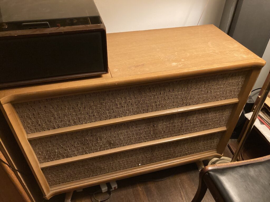
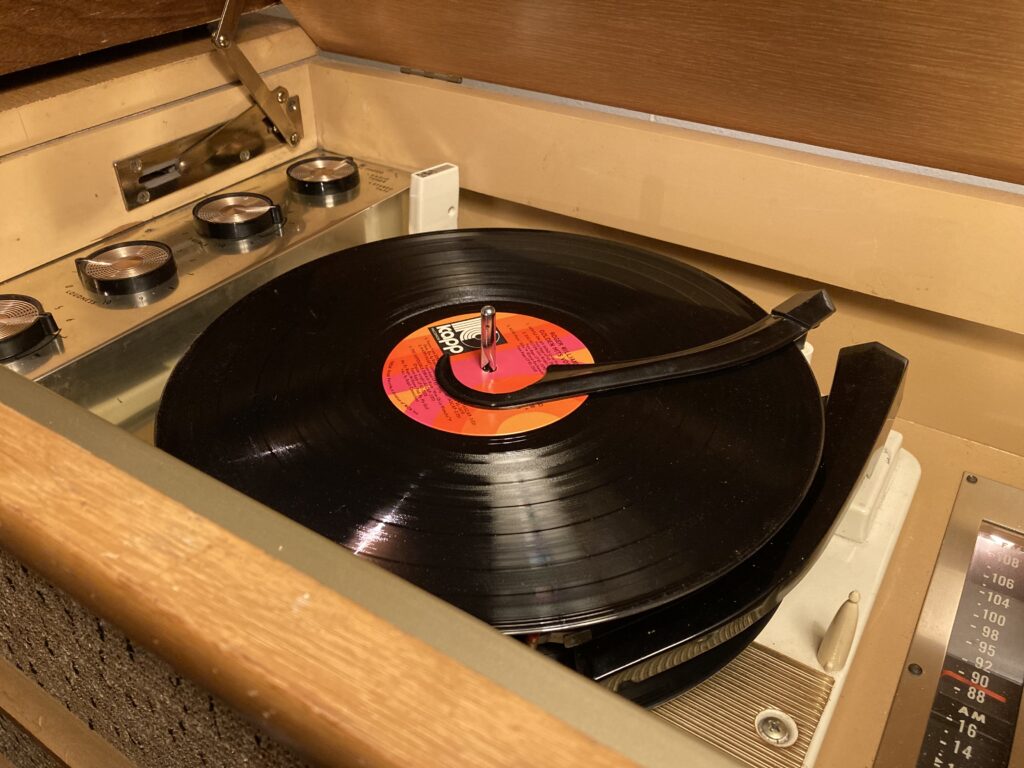
New to recapping, but not to electronics, I got a schematic. The console is Philco’s top of the line for 1959. Dubbed the “Phonorama V,” it is model G1907S. The ‘stereo’ option is really only for the phono, and it requires an external amp and speaker. The SA-3000 would be ideal, but I eventually managed to get the more lowly SA-1005 from 1960. I tore into it, and replaced ALL of the capacitors. The unit roared back to life. But the record changer, a VM 1220 (or similar), needed work. Bit by bit, over the years, I’ve worked on the changer, which works pretty well now, but needs a new motor if I ever want to get rid of the flutter. But the amp had a major problem. After being on for awhile, it started making popping noises. These noises were louder than the program, and eventually became stutters, called ‘motorboating’ in the trade, and took over. The only solution was to shut it down and let it cool off. In my ignorant zeal, I had replaced ALL the capacitors, even the small value ones in the input section. I’ve learned not to do that, but I had done it. I have long suspected these caps, but… after all, taking the console apart is a major chore, and I procrastinated. Since I had finally gotten the changer dropping records, even 45s, and found a decent replacement cartridge, recently, in my retirement, I got back down to it and took the amp out and got it on the bench again.
My idea, developed over the years of stewing about it, was that the resistors should really all be at least 1 watt. I had installed a few 1/4 watt jobbers in the front end. It seemed to me they might be heating up and changing value just enough to disturb the function of the resistor capacitor networks that did the work managing the small signals to the 12AX7 tubes. The amp generates a LOT of heat. It’s trapped in a box with a 15 inch woofer. It has a 5U4 rectifier and a pair of 6L6s. It’s not shy about swinging some volts.
So I replaced the resistors in a few locations, put in a cap with a higher voltage rating in one critical spot, in a network on the volume control center tap, and tacked the amp back in. I fired it up. Now, after the warm up, the amp skipped the popping and went right to motorboating. In the lead up to failure, it sounded just fine. The motorboating was at a different frequency than it had been.
So I left the amp tacked in, and the covers off, and went down to the shop to actually measure some of these caps I’ve been throwing into projects like candy into trick-or-treat bags. Guess what? They’re not even close to being the values they say they are!
I think the Chinese are trying to kill us.
I cobbled together some correct values by measuring and, where necessary, making collections of caps in parallel. That did the trick. The amp now performs properly. Mostly. The pots themselves are noisy.
And there’s that motor for the changer…
But wow. I’ll bet a few of my other failures can be blamed on these incorrectly labeled components.
Just wow.
