I’ve written about Salvatore Martirano’s SalMar Construction, as one who has performed on the instrument. The last time I was invited to do this, I had the notion that it’d be sweet to come up with a performer’s manual for that beast. It is not easy to learn, and very easy to forget what you have learned. Also, the instrument has evolved both subtly and radically as Greg Danner has worked on bringing it up to its former glory. By way of making a manual, I bought a copy of Sal’s alleged ‘bible,’ Malmstadt’s Digital Electronics for Scientists, hoping that reading and understanding this book would help me understand Sal’s process, and further, give me an insight into what the SalMar construction is, and could be. Mark Smart’s excellent simulation for NI’s Reaktor has much to teach regarding the SalMar’s architecture, particularly that the complex instrument is also patchable, and the present patch is a a relic in the sense that, say, Dickens’ “empty chair” is a relic. The master that once occupied that throne is gone; the mind that made the Construction speak is silenced. We may sit in the chair, complete the circuit, call up the TTL demons, but we best not re-patch the panels.
So I let myself be seduced by Malmstadt, perhaps the same way Salvatore Martirano had. I began to wonder how I might myself construct something using current digital technology and languages. Soon, I moved from wondering into practice, though the whole process got started in a random, haphazzard way. I have had a few Beaglebone Black single board computers floating around, one of which contained an attempt to make a looper, and so much water had gone under that bridge that I don’t know whether it looped audio or MIDI. It also ran an early bit of python code that drove some relays turning the lights on and off in my office cubby on a schedule. Crontab. The matter became moot, because I attempted to upgrade the operating system which had become a bit of a security liability, and ended up wiping the machine. Trying to resurrect that code meant going back over the Beaglebone cookbooks and getting back into the platform. Things have evolved in Beagle world since 2010! An eternity in tech years! Now, you can Google your way to Beagle nirvana and AI will help you with your Python!
One of the headaches I had with the Beaglebone was with the audio cape and its software ‘device tree overlay.’ Resurrecting the platform for further use brought these old nightmares back up to the surface. The mighty Google proved that the operating system has moved on, leaving my old bones in the dust. The capes are also deprecated. A decade is a century in computing years. A current path, which I explored for a spell, was the Bela platform. The Bela cape is not cheap. It can be extended with a sophisticated line of sensors and input/output (henceforward, io) devices, including MIDI and multichannel audio. The sensors are part of a package called Trill. I bought a few of the Trill sensors, and explored programming them using various flavors of Miller Puckette’s Pure Data, (Pd), an object oriented programming language. Several impediments to maker nirvana arise when using the Beaglebone/Bela/Pure Data system of instrument design. First, regarding Bela, as noted, is the price. Secondly, the Bela architecture allows programming in several languages: C++, Csound, and Pd. I’m not adept at Csound. The Pd interface is not real time, as Csound is. That is, you must program, upload, then compile and test. C++ and Csound can run on the fly. They are not object oriented, they are closer to what the compiler can turn into machine language. Finally, the Beaglebone is not protected from the users electrical mistakes. I blew up at least 3 boards, one after only one boot up! Which, of course, adds to the price of making. Still, I made some things with the Bela system, and will continue off and on to explore it.
Fooling with Pd, I was led, naturally, back in to Max MSP. Max is the commercial development of the open source Pd. Max is owned and distributed by Cycling’74, and is quite mature by now, “now” being version 8.6. I own Max 8x, but to I felt compelled to bring it up to date and get back into it. Once I was using Pd and Max MSP again, I began working through the many web sites and youtube tutorials on MIDI and audio. The first such that I made a solid connection with was Sound Simulator on youtube. His tutorials involve passing data back and forth between Max MSP/ Pd and Arduinos. One such project he calls the Ribbon Synth. It was here that I found my inspiration to make an “instrument.” When I say instrument, what I’m really talking about is a controller. There are several ways of controlling synthesizers modules in this context, and I’ll cover them one by one. Martirano had his collaborators, and, via the collegiality of the internet, I had mine.
I began with an iteration of SS’s ribbon synth, which I’m calling the “Rhybbon I” or, less pretentiously, ‘Rhybbon 1.’ It’s not a synth, in truth. Neither was SS’s. It is a ‘controller.’ Synths generate sound, controllers control synths. Synths, of course, can have controllers built in: keyboards, modulation wheels, buttons, pots, and various other sensors. Light sensitive resistors make good sensors; so do force sensitive resistors (FSRs), and, of course, Linear SoftPots… aka, ‘ribbon sensors.’ SS’s idea, which I adopted, was to layer the ribbon over the FSR. I also added: 3 big arcade style buttons, three rotary potentiometers (pots), and an array of switches. A digital to analog converter, (DAC), the MCP4728, is included to generate control voltages for modular synth control. Modular synthesizers are sold as discreet components, and rely on external control. There a a few standards for control, and the one I’m using is voltage control, 0 – 5 vdc. There is also a MIDI din output. The coolest feature, present in SS’s video, is the neopixel led strip. The 60 leds are too long for the SoftPot, so in the sketch only 40 or so are active. More could be done with this. For example, it would be even cooler if color changed along the line as force is applied to to the FSR. Another idea for later…
The microprocessor chosen for the Rhybbon 1 is the Arduino Pro Micro. These can be obtained from China on Amazon. (Because that’s a commercial link, I fully expect it to go dead at some point. But the reader will get the idea.) For the $ that one pays to SparkFun, you can get three of the Chinese knockoffs. My policy is to buy some from each. I hate starving vendors like SparkFun, and Adafruit, which provide all sorts of useful information as well as products. The DIY community cannot thrive without them. But to bracket multiple microprocessors loaded with various implementations of code, it’s good to have an ample supply of boards on hand.
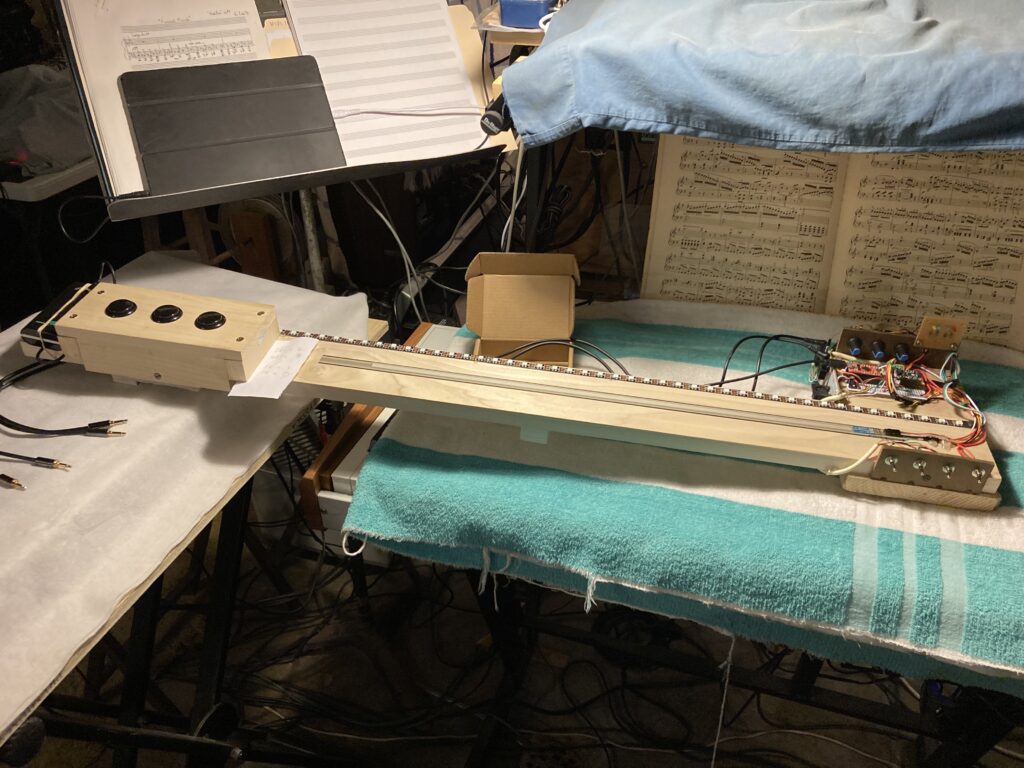
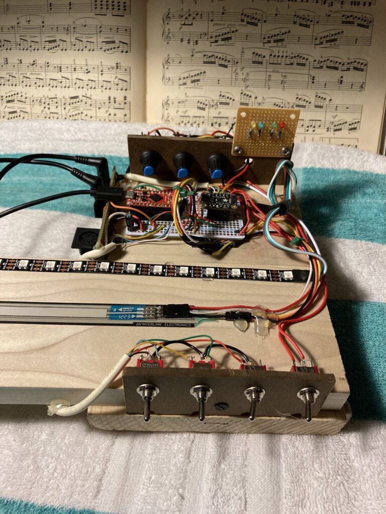
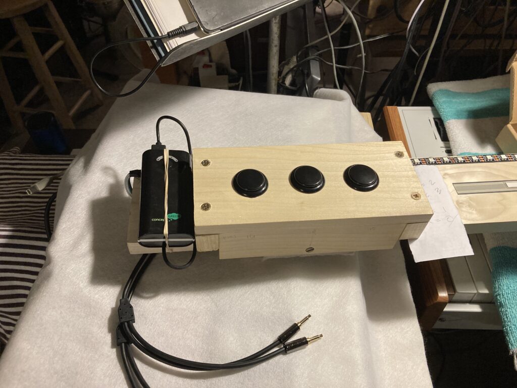
Left: the control center of the Rhybbon 1.
Above: The big buttons. Intended for rhythm sample playback, on MIDI channel 10, or, in software, ie., Max MSP.
The software in SS’s model was for the following platforms/packages: Arduino, Pure Data, and Max MSP. As noted, Pd is free. Arduinos, once the hardware is purchased, are programmed with the Arduino IDE, which is very much like Processing, but is dedicated to programming the Arduino family of microprocessors. As far as doing things with the output of a controller, one can, as noted, work with control voltage, MIDI (the Musical Instrument Digital Interface, around since the early 80s), or, if one wishes, one can use a package on a computer to turn the generated data into sound. (SS’s approach.)
I did indeed experiment with various flavors of Pd. But, as noted, I own Max MSP… so…
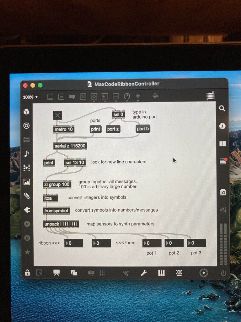
The Arduino code can be designed to send a data stream over USB (serial). The above screen shot shows a Max patch that reads the serial port, uses a clock (metro) to take snapshots of the incoming stream, and then convert it to numbers we can use to do stuff.
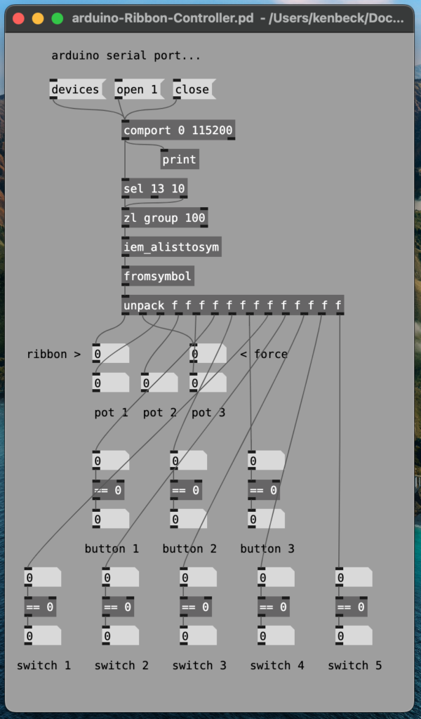
In order to use the raw data, it must be sifted into two basic categories. First, and easiest, there are the two positions represented by each switch. On = 1, off = 0. The only issue here is the matter of ‘bouncing,’ and that is corrected on the Arduino side, using a switching library called “bounce.” As with all the electronic devices involved, there are various conditions that must be met for functionality. In the case of switches, a switch in the off position connected to the positive rail (five volts, in the case of all the Arduinos used in this project), will ‘float’ unless forced to ground by a pull down resistor. The Arduinos themselves have built in resistors on every digital pin, which can be used as a pull up resistor. This inverts the logic: a switch is wired to ground and pulled up to the voltage supplied by the data pin. Thus, one uses ‘pin mode pull up’ (PINMODE_PULLUP) in declaring the pin function in the Arduino code. Secondly, in the case of sensors that function like pots, the poles of the resistor are at Ground and 5v respectively, and the wiper is connected to an analog pin. Instead of being on or off (1 or 0), analog pins give a numeric output. In the Arduinos I used, this is a number from 0 to 1023. Once I had data flowing from the controller to the computer as a serial stream, and had parsed that data into 1s and 0s, or numerals from 0 to 1023, the task became what to do with the data.
I used various models to arrive at patches in Pd and Max that I could use…
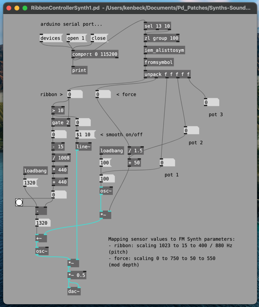
Since I was by now well familiar with SS’s site (youtube), I used his patch in Pd above as a way of getting some feel for the hardware I had assembled as a musical instrument. This exploration went slowly because of the several varieties of the Pure Data software competing for time and attention, all needing externals and massaging to run the patch successfully. Shown is the L2Ork flavor of Pd. This process led me to explore Max MSP. I looked for suitable synths that could be modified to work with the controller. Ian Hattwick’s was promising:
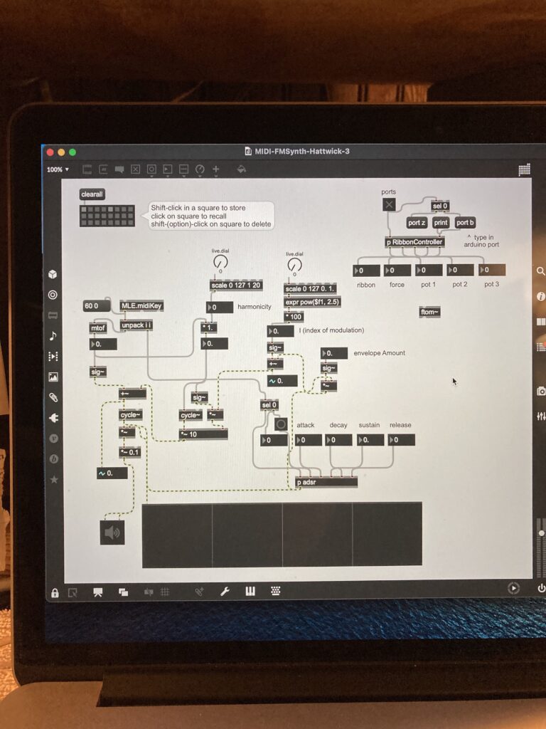
And from each of these models, I learned a bit more. FM synthesis is very rich in timbral possibilities, and at some point I’ll have to return to it. However, I was in ‘overview of the field’ mode, and thus worked through Oliver Thurley’s tutorials. Thurley offers a model of additive synthesis, in which waveforms are added to arrive at a much more complex waveform. The example shows that I used sine (the ‘cycle’ object), triangle, sawtooth, and two objects called ‘phasor’ and ‘rect.’ The phasor object generates a sine wave, and its left inlet sets the frequency of the waveform. The right input modifies the phase. Rect, similarly, is a rectangle wave generator, where there are three modifying inputs. From L to R: frequency, pulse width, and a sync input, so that the pulse width can be synced to a clock.
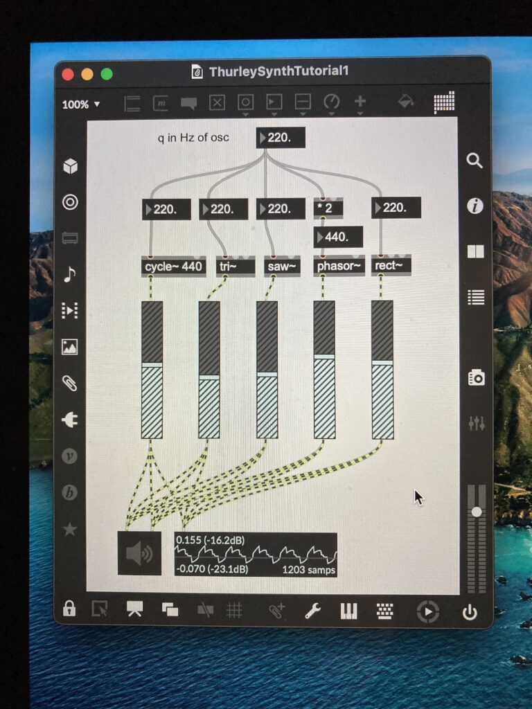
These screenshots offer a taste of what programming in MasMSP or Pd is like: these are object-oriented languages.
The Rhybbon 1 controller is also capable of two other methods (besides USB serial) of outputting its data. In all instances, an Arduino sketch is uploaded to the ProMicro, and that sketch governs the overall functionality of the controller. The other methods of control available by virtue of the hardware are: 1). MIDI over USB, and 2). Control Voltage (CV), 0-5v DC +. The MIDI over USB is a feature of the specific microcontroller and design of the ProMicro. When programmed to use the feature, the board complies with MIDI over USB protocols, and shows up in external software (ie., Logic, Ableton Live, and, of course, MAXMSP) as some variant of ‘arduino promicro.’ The specific MIDI info available depends on the Arduino sketch. CV, also sketch dependent, is available via eurorack friendly mono mini tip/sleeve plugs. There are four channels of CV. I have more or less settled on sending the output of the FSR and SotPot on the first two channels, with 0v to the left, and 5v at the extreme right. The FSR output is also scaled, but of course is independent of position. The harder one presses on the FSR, the higher the voltage. What these parameters control on a CV synth depends on where the voltages are applied on the synth. The remaining two channels are controlled by two of the pots. They are thus limited in their realtime control utility. That’s not to say that one can’t give these knobs a quick tweak on the fly in performance.
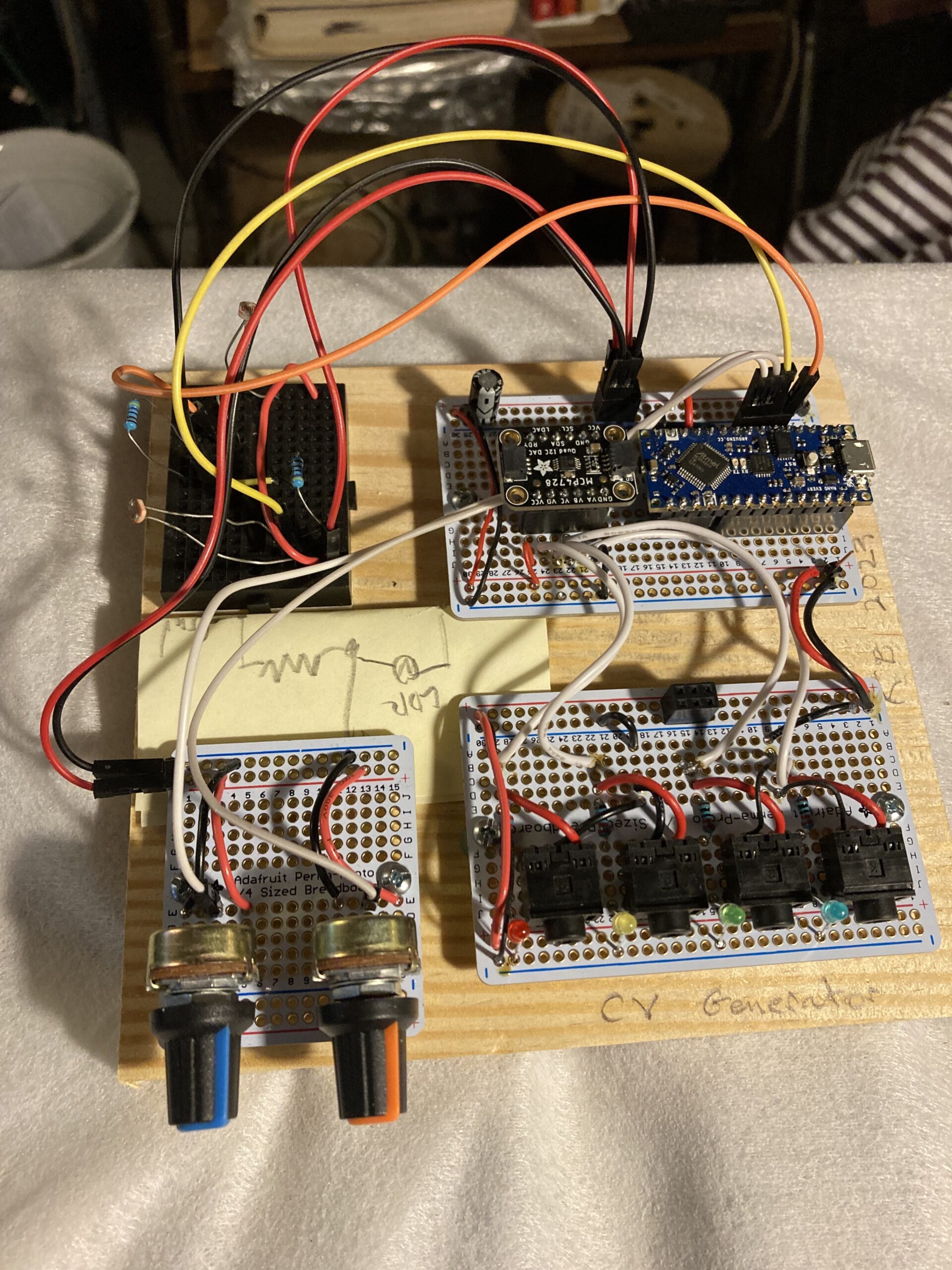
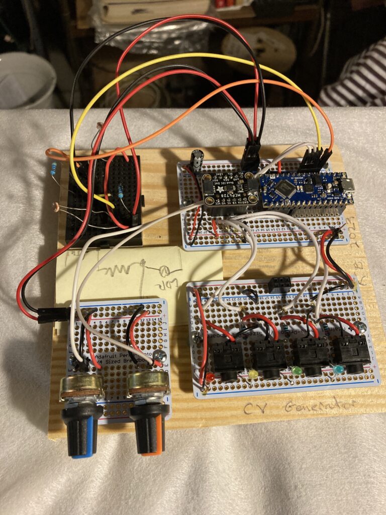
At the top of the post, you see an example of one of the ‘stepping stone’ builds. It is a stand-alone (ie., not multi-functional) single purpose control unit dedicated to generating control voltages. It makes use of an Arduino Nano Every, and an MPC4728 DAC. It has two pots connected at a patch point to channels 1 and 2, but it also features a mini breadboard where any other sensors could be added. At present, the two remaining channels are modded by a pair of light sensitive resistors, aka, ‘photocells.’ These are the best bang for the buck as sensors go; a couple of these in tandem (parallel, to form a voltage divider) with a resistor and some variable light source is all you need to get CV.
Having completed the Rhybbon 1 build, I was still restless and searching for DIY controller nirvana. Perfection might be impossible, but since the parts are fairly cheap, I thought I’d go for a Rhybbon 2…
